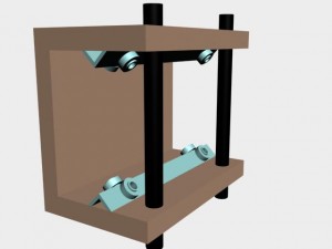
This morning I got up really excited about designing the parts for my cnc router. I fired up AutoCad and loaded up the website that contained the pictures of a machine design I wanted to pattern my machine after.
The design I’ve chosen for my machine consists of a series of C-shaped components that house aluminum angle to which skateboard bearings are attached that roll along two lengths of black steel 3/4″ pipe.
The machine will be designed using a gantry for the Y-axis that carries the Z-axis. In the gantry design, the Y-axis and Z-axis both move along the X-axis providing a 3-axis cutting motion. The linear bearings are designed using pieces of 3/4″ aluminum angle to which four skateboard bearings are attached.
I should be able to complete the design of the Z-axis today using AutoCad. This axis uses 3 pieces of medium density fiberboard (mdf), two linear bearings, and two short pieces of black steel pipe so it shouldn’t take too long to get the drawings complete.
When you come back, I should be well on my way to having the drawings done for the Y-axis and we’ll talk a little about that part of the machine. Until next time, stay safe, work hard, and as always, thanks for stopping by.


